Instructions for the Lexmark T644, T642, T640 Printhead Replacement
Really this article is for the Lexmark T644, T642, T640 Printhead Replacement so I’m not going to get into lots of details about the different errors and what they mean. Below you will find a list of the errors associated with the printhead. Also, throughout this article you will find links to getting a replacement printhead. If you are having problems seeing the pictures click on them for a blown up view of them.
Error Codes Related to the Printhead
930 .00 An incorrect printhead has been detected
932 .00 Printhead lost HSYNC.
933 .00 Mirror motor locked, no first HSYNC received.
934 .00 Mirror motor lost lock
936 .00 Mirror moor not up to speed

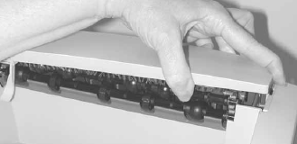
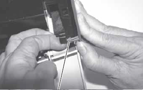
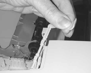
Redrive cap cover removal
1. Pull up on the right side of the redrive cap cover to remove.
2. Remove the redrive cap cover.
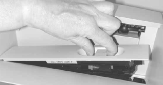
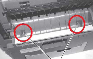
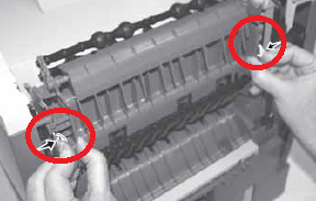
Fuser wiper cover assembly removal
1. Squeeze the two latches together, and pull up.
2. Remove the fuser wiper cover assembly.
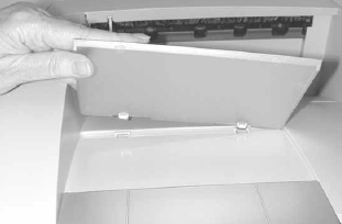
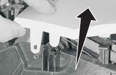
Paper support removal
1. Raise the paper support, and lift to release the latches.
2. Remove the paper support.
Left door removal
1. Open the upper and lower front covers.
2. Press the two left door latch buttons, and open the left door.
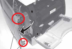
3. Release the top hinge from the latch.
4. Lift the door to release the bottom from the pin, and remove the door.
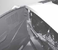
Redrive door
1. With the redrive door partially open, lift and free the left side.
2. Remove the redrive door.
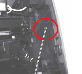
Right cover removal
1. Open the upper and lower front covers.
2. Remove the print cartridge.
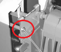
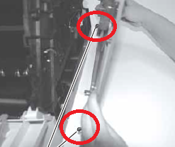
3. Remove the right front cover mounting screw.
4. Remove the redrive door.
5. Remove the two screws.
7. Remove the right rear cover mounting screw.
8. Press the two latches to remove the redrive assembly.
9. Press the latch firmly to release the front of the right cover.
8. Pull up and out on the right cover to release the three cover retainers at the bottom.
Note: When replacing the right side cover, make sure the three cover retainers are correctly located in the appropriate slots in the right side frame.
Top Cover Removal
1. Remove the screw at the rear of the printer and the larger screw at the front on the right side.
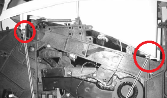
2. Remove the two mounting screws from the left side.
3. Remove the paper bin full sensor flag from the mounting bracket.
4. Unlatch the front right and front left cover posts, and remove the cover.
Lexmark T644, T642, T640 Printhead Replacement
CAUTION: The laser scanning unit is not a serviceable FRU. Replace the entire unit when service is required.
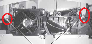
1. Disconnect the printhead cable from the printhead assembly.
2. Remove the three printhead mounting screws, and remove the printhead.
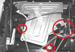
Note: Do the “Printhead assembly adjustment†whenever you remove or replace the printhead assembly or loosen the mounting screws.
–
Printhead assembly adjustment
Do the printhead assembly adjustment whenever you remove or replace the printhead assembly or loosen the mounting screws.
Install the new printhead with the three mounting screws centered in the slots in the printhead frame assembly.
Leave the screws loose enough to allow the printhead assembly to move from side to side within the slots. It is necessary to perform a registration adjustment before locking down the three printhead mounting screws.
To perform the registration adjustment:
1. Turn the printer off.
2. Press and hold the BACK and SELECT buttons.
3. Turn the printer on, and release the buttons when Performing Self Test displays.
4. Select Registration from the menu.
5. Select Quick Test Page. The test page should only be printed on letter or A4 paper from Tray 1. The Quick Test Page consists of alignment diamonds, horizontal lines that can be used for skew adjustment, page count setting, printer serial number code levels, and print registration settings.
6. Check the Quick Test Page for any sign of skew by checking the diamonds at the top left and top right of the test page for equal distance from the top of the page. If necessary, adjust the left or right printhead mounting screws and check the skew again by running another Quick Test Page. This procedure may take two or three attempts before you get satisfactory results.
7. When you have the correct adjustment, gently tighten the printhead mounting screws, being careful not to move the printhead assembly