Xerox ColorQube 8570, 8870, 8580, 8880, 8700, 8900 Drum Wiper Blade Removal

Xerox ColorQube 8570, 8870, 8580, 8880, 8700, 8900 Drum Wiper Blade Removal
Below you will find the Xerox ColorQube 8570, 8870, 8580, 8880, 8700, 8900 Drum Wiper Blade Removal Procedure. I’ve been seeing more and more problems with these units as they age. In some cases the wiper blade comes detached and will cause smudging. Other times, so much build up gets on the blade that the drum doesn’t get proper lubrication and while cause poor ink transfer and ghosting down the page.
The two things that I really watch when doing this repair are to make sure that when I remove and install the maintenance unit that I don’t touch the surface of the drum with anything, especially the metal of the unit, and installing the wire back through the frame hole can be annoying. The main thing is to have patience and take your time. The instructions can be overwhelming but if you look at the pictures in the middle of the article that might make it less confusing and easier to handle.


Xerox ColorQube 8570, 8870, 8580, 8880, 8700, 8900 Control Panel Cover Removal
Use care not to damage the Control Panel Wiring Harness while removing or replacing the Control Panel Cover.
CAUTION
Do not disconnect the ZIF cable and remove the Control Panel unless necessary, as the Control Panel connector is fragile and can be easily damaged, even when correctly following the replacement procedures.
1. Open the Exit Cover.
2. Open the Front Door.
3. Using either your fingers or a small flathead screwdriver, loosen the Control Panel Cover on the left side, and then slide the Cover forward while lifting up to remove it from the printer.
4. Pull the Maintenance Unit out from the printer.
Xerox ColorQube 8570, 8870, 8580, 8880, 8700, 8900 Right Side Cover Removal
1. Remove 1 screw (metal, T-20) that secures the Right Side Cover.
2. Pull the Right Side Cover forward to release the hooks located near the AC connection
and release the front hook while pulling the Right Side Cover outward at the top.
Xerox ColorQube 8570, 8870, 8580, 8880, 8700, 8900 Inner Simplex Guide with Pre-deskew Sensor and Harness Removal
1. Open the Front Door.
2. Remove the Lower Inner Duplex Guide.
3. Pry inward on the 2 retainers to release them from the mounting post.
4. Disconnect the wiring harness connector P/J128 from the Inner Simplex Guide. Release the wiring harness from the Inner Simplex Guide.
5. Slide the Guide down and forward to remove it from the chassis.
Replacement
Position the fingers on the Inner Simplex Guide over the segment roller. Install the Guide by
snapping the left side to the retaining post, then the right side.
Ensure switch wiring harness is routed through the restraints.
Xerox ColorQube 8570, 8870, 8580, 8880, 8700, 8900 Lower Inner Duplex Guide Removal
1. Pull the tabs at the bottom of the Guide forward and let the Guide swing free.
2. Pry on the right, upper retainer inward, towards the center of the printer, to release it from the boss and remove the Guide.
Xerox ColorQube 8570, 8870, 8580, 8880, 8700, 8900 Drum Cooling Fan Removal
1. Disconnect the Drum Fan wiring harness connector P/J903 from the I/O Board.
2. Remove 3 screws (plastic, T-20) that secure the Drum Fan to the chassis.
3. Remove the Drum Cooling Fan.
Replacement
NOTE: Check that the grounding strap contacts the Pivot Plate Shaft following installation.
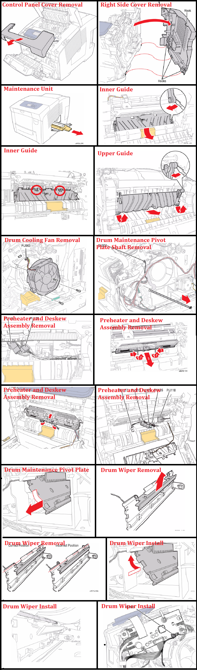
Xerox ColorQube 8570, 8870, 8580, 8880, 8700, 8900 Preheater and Deskew Assembly Removal
1. Disconnect the Paper Preheater wiring harness connector P/J115 and the Preheater
Sensor wiring harness connector P/J125 from the Preheater and Deskew Assembly.
NOTE: Note how the wiring harnesses are restrained to the printer frame bottom for reinstallation.
Use care when removing the Preheater. Do not pry the Preheater from the printer to prevent damaging the Preheater.
2. Slide the latches in and forward to release the Preheater as shown in Figure 2.
Replacement
Orient the wiring harness flat in under the Preheater, then gently insert the Preheater into place. DO NOT force it. Once fully inserted, release the latches to secure the Preheater to the printer frame.
Be careful not to release the spring under the wiring harnesses when dressing the wiring harnesses.
Be sure to dress the wiring harnesses under their tabs and routing guides.
The fingers on the Inner Simplex Guide go over the Deskew Roller. To install, first snap the left retainer in place, followed by the right. Make sure the sensors are properly positioned when completing the installation.
Xerox ColorQube 8570, 8870, 8580, 8880, 8700, 8900 Drum Maintenance Pivot Plate/ Drum Wiper Blade Removal
NOTE: Be sure to place a sheet of paper through the front of the printer between the Drum Assembly and the Pivot Plate Assembly to prevent damaging the Drum while removing the Pivot Plate Assembly
1. Push the Ground Plate out of the way to get access to the Shaft.
2. Disconnect the wiring harness connector P/J901 from the I/O Board.
NOTE: For the following step, be sure to keep the C-Clip attach to the shaft.
3. Pull the shaft out from the chassis,
Figure 1 Removing the Shaft
4. Feed the wiring harness through the hole in the chassis near the front of the Drum Assembly while sliding the Plate downward and out from the Drum Maintenance drawer cavity.
Xerox ColorQube 8570, 8870, 8580, 8880, 8700, 8900 Drum Wiper Blade Removal
1. Lift and remove the Drum Wiper Blade Assembly from the Drum Maintenance Pivot Plate.
Replacement
Be sure to place a sheet of paper through the front of the printer between the Drum Assembly and the Pivot Plate Assembly to prevent damaging the Drum while installing the Pivot Plate Assembly.
Do not unravel the wiring harness from the harness clips on the Pivot Plate. Be sure the Blade sits towards the edge of the Drum Maintenance Pivot Plate as in Figure 4. Verify the blade position.
Be careful to avoid touching the blade against the Drum.
Be sure to tilt and insert the Drum Maintenance Pivot Plate upward while holding the Pivot Plate from the rear.
Be sure to align the shaft with the hole on the left side printer frame.
Be sure to verify that the space between the Blade and Drum Assembly is even from one end to the other end at 1/4 in. (6 mm). There should be about a quarter of an inch level space between the Blade and Drum.
Check that the right end of the Pivot Plate Shaft is in contact with the Ground Plate following installation of the Drum Fan.
Be sure to connect the wiring harness connector P/J901 to the I/O Board.