Instructions for the Canon MF6590 – MF6530 Fixing Unit Removal Procedure
Paper jams in the fusing unit area are dang near impossible to remove without removing the fixing unit. If you ever look at these machines then you would think the fixing unit comes out easy but that is not the case. These things can be a pain to remove and if your not careful you can break the exit drive gear shaft. Therefore, below you will find the Canon MF6590 – MF6530 Fixing Unit Removal Procedure instructions along with pictures to help make the job easier. Now I did not include removing the back and front covers and the left side covers as that is easy to figure out compared to the fixing unit. If you can’t figure those out then you probably shouldn’t be removing the fixing unit.
–
–
–
–
–
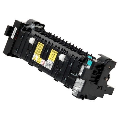
Fixing Unit Removal
The height of the fixing unit is adjusted at 2 mounting points at the front (left door + front cover) prior to shipment. If you need to detach the fixing unit, apply 2 markings before detaching the unit to enable you to return the unit to its previous position. When replacing the fixing unit with a new one, carry out height adjustment.
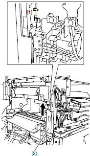
1. Detach the rear cover and front cover, and then detach the rear-left cover.
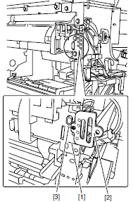
2. Remove the boss, and then slide the guide (front) to remove it.
–
–
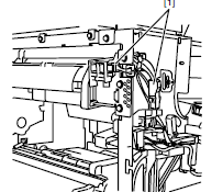
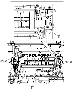
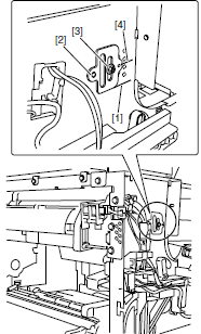
3. Disconnect the two connectors, and then release the cable from the clamp.
4. Remove the screw and remove the fan duct.
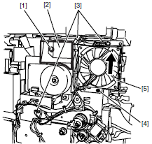
5. Remove the three connectors and one screw, and then slide the fan unit upward to remove it.
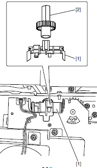
6. Remove the boss, and then slide the guide (rear) backward to remove it.
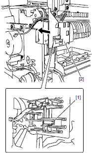
7. Release the hook, remove the fixing gear retainer, and then remove the fixing gear.
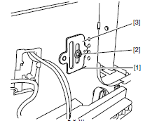
8. Apply marking, remove 1 screw, and detach the positioning pin.
9. Apply marking, remove 4 screws, and detach the fixing unit.
Installing the fixing unit
1. Install the fixing unit without tightening the screws.
2. Install the positioning pin to align with marking at the left door, and then fix it with 4 screws at the front and back of the left door. When installing a new fixing unit, install the positioning pin to align with reference mark.
4. Remove the positioning pin.
5. Install positioning pin to align with marking at the front cover, and then fix it with one screw. When installing a new fixing unit, install the positioning pin to align with reference mark.
6. Perform the following procedure by reversing the installation procedure.


Need to know how to take the fuser apart to replace fixing sleeve. Thank you, Larry