Okidata C610 Fusing Unit Troubleshooting Tips
Below you will find advanced Okidata C610 Fusing Unit Troubleshooting Tips. 95% to 99% of your fuser errors will simply be fixed by replacing the fusing unit. However, if you have time to kill or you think your problem might be the exception to the rule then check out the repair tips below.

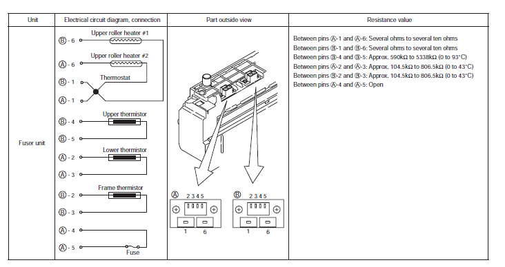
Fuser unit error (error 170 to 177)
Error occurs immediately after the power is turned on.
Thermistor is defective Note
Upper thermistor,
lower thermistor,
frame thermistor
Check the respective thermistors if they are shorted or opened internally.
Check the resistance value at the connector pins in the bottom of the fuser unit.
Replace the fuser unit.
If any attempt of using new fuser unit as a trial is going to be made, be sure to use the System Maintenance Menu FUSE KEEP MODE.
Installed condition of fuser unit.
Check if the fuser unit is pressed in until the connector in the bottom of the fuser unit is surely connected.
Re-set the fuser unit.
Note! Service calls 171 error and 171 error can occur when the printer temperature is below 0 . Turn on the power again after the printer temperature has increased.
Error occurs approx. 1 minute after the power is turned on.
Temperature increase of fuser unit
Thermostat, halogen lamp
Heater of the fuser unit is controlled of its temperature. Check if the fuser unit gets hot or not by touching it with hands.
If the fuser unit temperature does not increase and remains cold, check that the resistance between pin-1 and pin-6 of connector A, and that in between pin-1 and pin-6 of connector B of the two connectors is in the range of several ohms to several ten ohms respectively.
Replace the fuser unit.
If any attempt of using new fuser unit as a trial is going to be made, be sure to use the System Maintenance Menu FUSE KEEP MODE.
Temperature increase of fuser unit
Installation position of the upper thermistor
Check if the upper thermistor is installed in the far position from the specified position or not causing detection of the lower temperature than the actual temperature of fuser unit.
Remove the heater cover, and check warpage of sensor by visual inspection.
Replace the fuser unit.
If any attempt of using new fuser unit as a trial is going to be made, be sure to use the System Maintenance Menu FUSE KEEP MODE.
Installation position of the lower thermistor
The lower thermister must be installed while contacting with the fuser unit. Check if the lower thermister is installed in the far position from the specified position or not causing detection of the lower temperature than the actual temperature of fuser unit.
Replace the fuser unit.
If any attempt of using new fuser unit as a trial is going to be made, be sure to use the System Maintenance Menu FUSE KEEP MODE.
AC power input to the halogen lamp
AC power voltage from the low voltage power supply
Check if the AC voltage for heater is normally supplied or not.
Power supply CN2 connector , between pin-1 and pin-2, and between pin-3 and pin-4.
Replace the low voltage power supply.
Heater ON signal that is output from PU to the low voltage power supply
Check that the heater ON signal goes active at the warming up timing, or not.
“L” active while ON.
Power connector of the CU/PU board, between pin-14 and pin-15.
Replace the CU/PU board.
Click on the link below for fuser replacement instructions
Okidata Color C610 , C711 Fuser Replacement – 44289101