Instructions for the Lexmark T654, T652 Printhead Replacement Procedure – 40X4464
This article is pretty straight forward. you want to perform the Lexmark T654, T652 Printhead Replacement Procedure, here it is. Below you will find the error codes associated with the printhead on this machine. Also, you will find a few links on this page to order a replacement printhead if you still need to get your hands on one.
Printhead / Laser Scanner Related Error codes
Error Code 930.00
Error Code 931.00
Error Code 932.00
Error Code 933.00
Error Code 934.00
Error Code 935.00
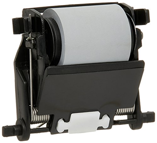
40X4464 – T652, T654 Lexmark Printhead With Cable Asm

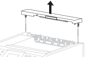
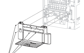
T654 and T652 Output cover assembly removal
1. Unsnap the output cover assembly from the machine.
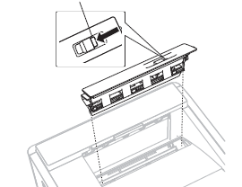
T654 and T652 Fuser wiper cover assembly removal
1. Press the button securing the fuser wiper cover assembly to the machine.
2. Remove the fuser wiper cover assembly
T654 and T652 Rear Lower Cover removal
1. Open the rear lower door.
2. Remove the four screws securing the cover assembly, rear lower to the machine.
3. Remove the cover assembly, rear lower.
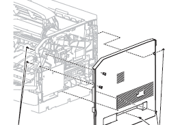
T654 and T652 Right Side cover removal
1. Open the operator panel door assembly.
2. Open the MPF tray door assembly.
3. Remove the five screws securing the side cover, right to the machine.
4. Remove the side cover, right.
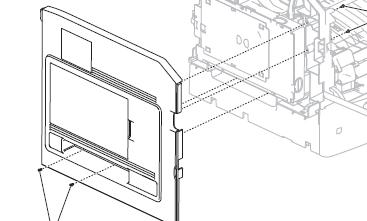
T654 and T652 Left Side cover removal
1. Open the MPF tray door assembly.
2. Open the operator panel door assembly.
3. Remove the four screws securing the side cover, left to the machine.
4. Swing the side cover, left away from the machine.
5. Remove the side cover, left.
T654 and T652 Laser cover removal
1. Remove the five screws securing the laser cover to the machine.
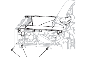
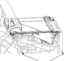
WARNING: When removing the laser cover, ensure that the standard bin actuator assembly does not become damaged.
2. Remove the laser cover.
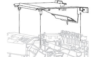
T654 and T652 Printhead assembly removal
WARNING: When replacing the printhead assembly, ensure that the printhead skew is properly adjusted, or print quality issues will occur.
1. Remove the six screws securing the metal cover to the machine
2. Remove the metal cover.
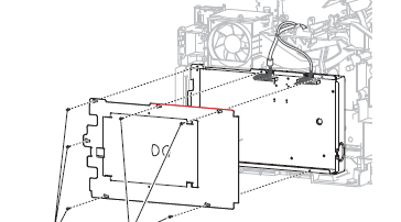
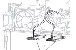
3. Disconnect the connections from the printhead assembly.
4. Remove the four screws securing the printhead assembly to the machine.
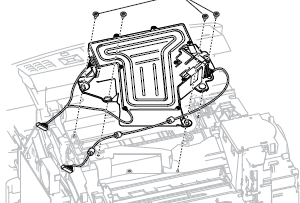
5. Remove the printhead assembly.
Replacement Warning: When replacing the printhead assembly, ensure that the printhead skew is properly adjusted, or print quality issues will occur
–