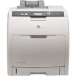
HP Color Laserjet 3000, 3600, 3800, CP3505 Left Side Lock Cartridge Problems
One of the more common issues with these HP color laserjet printers is broken lock lever or cam assemblies resulting in problems installing cartridges or 10.92.XX errors. In this article I’ll tackle cartridge problems with the left side of the lock lever and cam assembly because this is not near as hard as replacing the right side.
Majority of the time when these left lock levers or left cam lever break its easy to take the cartridge or cartridges out but when you go to put them back in the left side doesn’t want to fully insert. If your lucky the customer will quit there and say the have cartridge problems when installing a new cartridge. Unfortunately most don’t. If a person wants they can force the cartridge in which can break the lock levers if they are not broken yet or force the cartridge slightly to the right so it binds the MDA and or causes the cartridge to be permanently stuck inside the machine. At this point it’s usually time to call a service technician for you cartridge problems.
What Causes the Cartridge Problems and What to Look For
I’ve never broken a lock lever but from the design I believe two things can cause these cartridge problems. First would be not opening the door all the way to release the lock lever mechanism. So one would take the cartridge out and when they went to insert the new one the lock lever would be in the way so either they force the cartridge in or when they close the door it breaks the lock lever because it forces it back. Second and the one I see most often is a broken left cam assembly. When the left cam assemblies clip breaks the lock levers don’t move the way they should so once again it results in problems when you remove a cartridge and install a new one. So when ever you have a broken lock lever resulting in cartridge problems you must always check the lock lever cam assembly. The lock levers can be hard to find. If you open the front door, transfer assembly, and remove the cartridges. Now on the left and right side where the cartridges slide in place are lock levers to keep the cartridges from moving around. The black cartridge lock levers are light gray and the rest are black for the colors. If you look close when you open and close the transfer assmebly you can see the lock levers go up and down.
[contentblock id=2]
Fuser Removal
Open the upper cover, and then squeeze the two blue fuser-locking levers to release the fuser.
Rotate the fuser up and out of the printer.
Upper Cover
Once you have the fuser out you’ll see the two screws that were underneath and two more recessed just to the left and right of those screws. Note the two screws towards the out side of the cover are longer than the ones under the fuser.
Left cover
1. Remove two screws.
2. Open the front cover.
3. Use a flatblade screwdriver to release the three locking tabs at the front of the left cover.
4. Release the locking tab at the upper front of the left cover.
5. Release the two locking tabs at the rear of the left cover.
6. Rotate the back of the cover away from the printer, and then slide the cover to the rear to disengage the two front locking tabs and release the cover.
High Voltage Power Supply
Note: I’m lazy at this point. The service manual recommends removing the back cover and disconnecting the high voltage power supply cables from the DC controller. I’ve found that if I have enough room I can just lean the board up against the machine with out removing a lot more parts.
1. Remove four screws, and then disconnect two connectors.
2. Release seven locking tabs, and then remove the high-voltage power supply.
High Voltage Contact Assembly
1. Remove 3 screws on the left side and one screw on top in the front cavity of the machine.
2. Release the four black tabs; 1 top, 1 bottom, and two on the left side and pull the assembly toward the back of the machine and out.
3. Once the contact assembly is out the four lock levers, slide lever, and cam assembly are all exposed and easily removed.
The Cam assembly is at the bottom and meshes the transfer assembly and lock lever slide assembly so when you open and close the transfer assembly it moves the lock levers. The clip the holds the cam assembly in place on the metal shaft breaks resulting in the cam moving out and away from the slide assembly. So the cam still moves but it doesn’t lift and lower the lock levers. If you have a C or E clip you can install it on the metal shaft with out replacement but if your going to order the lock levers you might as well order the cam assembly.
Conclusion about the Cartridge Problems in the HP Color Laserjet 3000, 3600, 3800, and CP3505
Hopefully, this article has helped you solve your cartridge problems are your HP color laserjet. Replacing the lock levers on the left side is not really a bad repair. Now if you need to replace the lock levers on the right side and your not use to repairing machines then I would call a technician and have them do it. The MDA has to be removed just right and the gears have to be aligned just right when its reinstalled. Something not for the light-hearted and impatient.
Left Lever lock: RC1-6633, 3 needed
Left upper Lever lock: RC1-7618, 1 needed
Left Slide Lever: RC1-6636, 1 needed
Left Cam slide: RC1-6638, 1 needed
[contentblock id=1]
Find printer service newsletters, parts, and more at: http://www.partsnow.com/

